

Results 21 to 30 of 30
-
03-09-2014 #21
 Registered User
- Join Date
- Nov 2012
- Location
- Sacramento, CA
- Posts
- 1,918

Tuning the split in a panhard bar for neutral handling
For most road course & autocross applications, a watt's link works well and is the preferred choice of many. I agree & support this ... but because I'm a tuner, I prefer a panhard bar ... but only if it is height adjustable on both sides & centered in the chassis. This is not a thread to steer someone towards or away from either. Just an understanding of how they work & how they can & can not be tuned.
Pros & cons of Watt’s links:
• Pro: Does not cause different roll centers, roll resistance or tire loads on LH & RH corners.
• Con: Can not be tuned to provide different roll resistance or tire loads on LH & RH corners.
Pros & cons of panhard bars:
• Con: If simply set level, causes different roll centers, roll resistance & tire loads on LH & RH corners.
• Pro: Can be tuned with simple angle change to achieve neutral & equal roll resistance & tire loads on LH & RH corners.
• Pro: Can be tuned to provide different roll resistance & tire loads on LH & RH corners.
The natural tendency for a panhard bar (mounted to the housing on the left & the chassis on the right):
• In LH turns, the left side rod end raises only a small amount with tire extension & the right side rod ends lowers significantly with suspension compression. This moves the roll center down dynamically on LH corners.
• If the panhard bar had been level at 10”, the math could look like this: LH 10.25” & RH 9” = DRC 9.625” & 1.25” split
• In RH turns, the left side rod end lowers only a small amount with tire compression & the right side rod end raises significantly with suspension extension. This moves the roll center up dynamically on RH corners.
• If the panhard bar had been level at 10”, the math could look like this: LH 9.75” & RH 11” = DRC 10.375” & 1.25” split
The split is the same both directions … at 1.25” in this example:
• But the DRC (dynamic roll center) is ¾” lower on LH corners than on RH corners.
• The car rolls more on LH corners … making the car more free or looser.
• The car rolls less on RH corners … making the car more tight or pushy.
• If the panhard bar mounting is reversed, everything above is reversed too.
• This can be corrected easily. More on the “how to” later.
The irony is … the torque steer from centered 3-link, 4-link, torque arm & truck arm suspensions … behave the opposite under power on corner exit. So under power the combination of torque steer & panhard effects are neutralizing each other to some degree … but just on corner exit. You would still have the car behaving more freely or looser in the entry & middle of LH corners … and more tight or pushy in the entry & middle of RH corners. So it’s not the ideal solution by any means.
But with an offset 3-link … if the top link is offset to the right the correct amount to counter the torque … you end up with zero torque steer under power. Combine this with a Watt’s link or “Balanced Panhard Bar” and you will have even loading throughout the corner … on both left & right hand corners.
What is a Balanced Panhard Bar?
We already know that Watt’s links do not cause different roll centers or loads on LH & RH corners … and they can not be adjusted to do so. If you’re running a Watt’s link you will have even loading. If you’re running a panhard bar … with an offset 3-link … you need to tune the panhard bar angle to neutralize the effects discussed above and have a balanced panhard bar set-up. It is easy to do, but needs to be done.
To counter the typical panhard bar effects, you simply run angle … also known as split … in the panhard bar … with the left side lower & right side higher. (Assuming the panhard bar is mounted to the housing on the left & the chassis on the right.) For discussion purposes only, let’s say you run the same 10” roll center but with a 1/2” split. The left side would be 9.75” & right side 10.25”. The dynamic results during cornering would look like this:
• In LH turns: LH 10” & RH 9.25” = DRC 9.625” & 0.75” split
• In RH turns LH 9.5” & RH 11.25” = DRC 10.375” & 1.75” split
This next part throws people off as it is a little challenging to digest:
• The dynamic roll centers do not change with panhard bar split.
• But the differences in dynamic panhard bar angles … change the chassis roll resistance & tire loading when cornering.
• The lower levels of split on LH corners & the higher levels of split on RH corners … balance the handling left & right.
• Of course the numbers above are just an example & the split needs to be fine tuned on any race or track car.
So Ron … why don’t you run a Watt’s link?
Simple answer really. There are some variables that sometimes call for the race car to load the tires more one direction of corner & less the other direction. An adjustable panhard bar lets me fine tune the balance of tire loading.
Situations to tune balance with panhard bar split:
1. Car not 50/50 balanced side to side. Some cars are left heavy due to driver placement.
2. Some tracks have more rights. Some tracks more lefts.
3. Some tracks have high speed lefts & low speed rights … or vice versa.
4. Some tracks have more banked lefts & flatter rights … or vice versa.
5. Some track have off-camber corners, combined with flat and/or banked corners.
At the end of the day, winning races is about overcoming the challenges of the track better than your competitors. If I have a tuning tool that lets me tune for any of these 5 conditions better than my competitors that don’t have this tool … that’s an advantage I’ll take.
We ran a course with 7 right hand turns and only 2 lefts. One left was banked & the other was tight & flat. We used several tools to “wedge” the opposite direction of oval track racers. This gripped up the RH turns & freed up the LH turns. We had amazing grip on all the right hand turns. The banking providing “ok” grip for the first left turn. And freeing up the other super tight left corner made us faster there too. We were faster in 8 out of the 9 corners … won a lot a of races … and won two championships at that track.
---------------------------------------------------------------------------------
Whew! That’s a lot to take in. Let’s summarize it.
1. Centered 3-link, 4-link, torque arm & truck arm suspensions experience torque steer under acceleration.
2. Offset 3-links, if offset correctly, do not experience torque steer.
3. Watt’s links do not cause different roll centers or loads on LH & RH corners … and cannot be adjusted to do so.
4. Panhard bars do cause different roll centers & loads on LH & RH corners … but can be adjusted back to neutral & balanced.
5. Panhard bars can be run neutral & balanced … or tuned to load the tires differently if needed.
---------------------------------------------------------------------------------
With a centered 3-link, 4-link, Torque Arm or Truck Arms & a Watt’s link:
• You will have even loading on entry & middle for both left & right hand corners.
• You are stuck with torque steer on corner exits.
With a centered 3-link, 4-link, Torque Arm or Truck Arms & a adjustable panhard bar:
You can use the panhard bar angle to effectively counteract "torque steer" … to a degree. The keys to doing this are simple:
• Keep the center height where you want the roll center.
• Lower the side you want to load the tire more on & raise the other side the same amount.
This strategy is always a compromise. But the suspension already had a compromise.
You’re just shifting where the compromise is.
Think of it this way:
• If you eliminate 100% of the torque steer, you will have 100% of the effects provided by an unbalanced panhard bar set-up.
• If you balanced panhard bar set-up 100%, you will have 100% of the of the torque steer.
• Most racers shoot for a 50/50 balance and then tune for track conditions.
• You can always shift the balance to gain here & give up there.
With an offset 3-link & a Watt’s link:
• You have zero torque steer and can achieve a “Balanced Panhard Bar” for even loading throughout both left & right hand corners.
With an offset 3-link & an adjustable panhard bar:
• You have zero torque steer and can achieve a “Balanced Panhard Bar” for even loading throughout both left & right hand corners.
• Plus, you can tune tire load balance with panhard bar split if the situation calls for it.
Make sense?
Last edited by Ron Sutton; 05-22-2014 at 06:42 AM.
-
03-11-2014 #22
 Registered User
- Join Date
- May 2011
- Location
- Northwest, MO
- Posts
- 101
Ron, thanks again for your assistance. I almost always end up reading your posts multiple times, but you certainly are very good at providing concise explanations that break down the concepts. It was a lot of information to digest, but I think I have some grasp of the outlined concepts. Below are my answers to each of your questions, which I hope will clear up any confusion. Originally Posted by Ron Sutton

My Dad started experimenting with modifying the spindle steering arms. That project is finally to a mock up stage. Here is a picture. The spindle itself is the same, but the overall length of the steering arm is approximately 1" shorter than before, and the steering arm is bent as far as brake rotor clearance allows, which is about 2” further inward. The plan is to reset the alignment and then check and adjust bump steer as necessary. The basic goal is to try and at least eliminate the anti-Ackerman steering to achieve some percentage of 100% Ackerman. Originally Posted by Ron Sutton
One video was from GG Des Moines July 2012 and the other was from GG Kansas September 2012. I do not believe any chassis or suspension components were changed between the two events. It is possible that there was a slight change in the front end alignment between the two events though. Originally Posted by Ron Sutton
Those suspension view videos were taken with the old truck body. The truck body was slightly lighter in the front and lighter in the rear. The underlying chassis components are the same though. Originally Posted by Ron Sutton
This was the original setup that started as a stock style S10 front suspension with a conventional spring, stock style shock, and drop spindle. Originally Posted by Ron Sutton
At this point the ridetech Triple Adjustable Coilovers were installed with a 10" long 450 lbs/in spring (softer than the previous conventional spring). The stock style 28 mm S10 sway bar was used, albeit with aftermarket end links. This is the setup used in all of the videos I posted. Originally Posted by Ron Sutton
Correct. Originally Posted by Ron Sutton
The caster measurements were only recently taken using a newly acquired Fastrax gauge. I hope the error was in the cater measuring process. I will look into verifying both measurements. When my Dad and I mapped out the suspension, we spent the better part of a Saturday and Sunday making sure the measurements were accurate. Originally Posted by Ron Sutton
I would like to redo the entire front end with better components and ditch the heavy, cast Cragars for a set of 18” light weight forged wheels with deep backspacing, but for the time being I cannot afford to change or upgrade my wheels and all of the components so I am stuck reusing components in a different way or targeting aspects that can be tweaked or fabricated. Originally Posted by Ron Sutton
Dependent upon your input, I think tweaking the upper and lower control arms pivot points should be able to provide two benefits. First, (if I am picturing the dimensions correctly) I think it should be possible to square up a large amount of the front end geometry by tweaking the horizontal and vertical position of the upper and lower control arm pivots on either side. For instance, I double checked, and the ball joint pivots to control arm pivots are the same on either side. Second, where feasible, it might also be beneficial to improve the geometry rather than simply square it up. That said, I am not the expert here so I will defer to your suggestions. Originally Posted by Ron Sutton
Originally Posted by Ron Sutton
I will add measuring bump steer to the "to do list."
Yes, the concept makes sense. Originally Posted by Ron Sutton
Tyler Gibson
There's nothing like building up an old automobile from scratch and wiping out one of these Detroit machines... That'll give you a set of emotions that will stay with you... Know what I mean? Those satisfactions are permanent...
-
03-11-2014 #23
Registered User
- Join Date
- May 2011
- Location
- Northwest, MO
- Posts
- 101
It sounds like the current panhard bar split is the opposite of ideal. The housing mount on the left is a fixed design set at 9 5/8" and the chassis mount on the right is adjustable in 1" increments from 6 5/8" to 9 5/8" Originally Posted by Ron Sutton
At first, we usually just ran the panhard bar level but at one point it was disconnected and put back in the lowest hole (probably for no good reason). It should not be a huge problem to alter the current design of the panhard bar by either tweaking the mounting points or by fabricating new mounting solutions.Tyler Gibson
There's nothing like building up an old automobile from scratch and wiping out one of these Detroit machines... That'll give you a set of emotions that will stay with you... Know what I mean? Those satisfactions are permanent...
-
03-13-2014 #24
Registered User
- Join Date
- Nov 2012
- Location
- Sacramento, CA
- Posts
- 1,918
Hi Tyler,
We got a lot of conversation points going. I'll try to keep it concise & on track.
#4 - I like the "shorter arm" as that will speed up the steering. If you're not moving the steering box, arms & centerlink assembly back the same amount ... that will reduce the ackerman ... so it requires more ackerman be built into the spindle offset. Moving it in 2" may be overkill. Realize the centerlink adds some ackerman as it moves forward during steering (as the steering arms rotate).
You need to either calculate it out or test it physically on the truck. With zero toe-in or toe out, if you turn the wheels left ... and make the RF at a 25° angle ... what angle is the LF at? I often target 4-5° more.
#5 - It does make sense now. the two tracks could have easily had different grip levels and created different roll angles. Also, if you changed any alignment specs as you mentioned, could affect it too.
Later on ... switching back to the heavy body ... played a big roll in your roll angle being higher. Additional weight, up high, has to be dealt with.
#6 - Makes sense. When you went to softer springs & kept the small sway bar, roll angle increased along with dive travel. Now you've put on the bigger sway bar, which is a good move.
#8 - Either the ball joint measurements are off or the caster measurements are off, because they don't match. Double check & see if you can find which is correct.
#9 - I completely understand the budget issue. Work to optimize everything else & make it work as well as you can with the scrub radius you have now. Then, down the road, if you want to improve this area, you'll need to make new control arms & get deeper back spaced wheels.
#10 & #11 - You are on track. It is not that hard to square up the measurements ... and while you're at it, make some improvements. Lance Hamilton did this to his Monte and made big gains. Read his thread on how to do this HERE.
#13 - Doing the bump steer could show a small or big problem. So that is good it's on the "to-do" list.
#15 - You've already done something to improve this ... by switching to a larger front sway bar. Without running the calcs, we don't know if this achieves the optimum front to rear roll angles. And if you're going the low roll angle route, you have a decision to make in "how far". Let's say the 33mm bar reduces your roll angle from 3.0° to 2.5°. Do you want to fine tune that combo? ... or go to a bigger splined sway bar in the front and shoot for a roll angle of 2.0°, 1.5°, etc? ... and tune your spring & bar package around that?
Last edited by Ron Sutton; 05-22-2014 at 06:52 AM.
-
04-23-2014 #25
Registered User
- Join Date
- May 2011
- Location
- Northwest, MO
- Posts
- 101
Ron, I got your message so I figured I would check in even though I do not have much of an update. I am glad to see you are back on the forum, and I hope that your business venture is going well. I have not been home or had time to work on the Scout since February as I have been very busy with school, which is finally winding down after 20+ years. Once I graduate in mid-May, I should be able to devote some more time to the Scout. In the meantime, my Dad has tweaking the steering geometry and other components to get bump steer under control. I will also have the opportunity to attend two autocross events on June 1 and June 29 for gathering more testing data and video footage. Before I start, I had a carryover question from a previous post:
Ron, I forgot to ask this earlier . . . What sort of inputs of measurements, video footage, or other inputs are necessary to determine shock valving? And for the upcoming events are there any video angles or data I should focus on collecting? Originally Posted by Ron Sutton
The results were as you indicated above. With the wheels turned to the left and the RF at a 20° angle, the LF is also at a 20° angle (+ or - 1°). However, by further modifying the steering arm, the results improved and are closer to the target of 4-5° Originally Posted by Ron Sutton
I still need to set everything up for re-measuring the ball joint dimensions. Originally Posted by Ron Sutton
The tie rods were pointing above the instant center, which caused the wheel to bump-out when moving up, and bump-in when moving down. Using a very helpful Longacre document and a different centerlink, it was possible to get the bump steer under control using a design similar to the bottom diagram. For the time being though I do not have super accurate measurement numbers. Originally Posted by Ron Sutton
Here is a pic of the centerlink in mock up and a pic of the final product.
I probably would prefer to look into further reducing the roll angle with a larger splined sway bar if the 33mm sway bar only reduces the roll angle to 2.5°. I largely base this off information in some of your other posts, and under the assumption that you think it would be a good idea to further reduce the roll angle. In the past, I looked into a larger splined sway bar from Speedway Engineering. I think it would be a relatively affordable way to upgrade the sway bar and build in greater adjustment. The main problem will be packaging. If a larger splined sway bar is placed in the same position as the stock style sway bar, it might require arms with multiple complex bends to fit because the packaging is rather tight. That said, I think it should be feasible to fabricate a solution, and once the initial fabrication was done it would be relatively easy and affordable to fine tune the sway bar in the future. Originally Posted by Ron Sutton
This from an earlier post:
. Originally Posted by Ron Sutton
I apologize up front, because once again I am potentially opening up a new can of worms . . . But once the front end is in a happier place, my Dad and I thought it might be time to look at redesigning the rear suspension. When we first built the chassis it was a use what we had on hand project, closely followed by a go with what is easy to package and fabricate motto. I figure it should not be too hard to package a homemade offset 3 link for the rear that can offer more adjustability and less unsprung weight among other attributes.Tyler Gibson
There's nothing like building up an old automobile from scratch and wiping out one of these Detroit machines... That'll give you a set of emotions that will stay with you... Know what I mean? Those satisfactions are permanent...
-
04-23-2014 #26
Registered User
- Join Date
- Nov 2012
- Location
- Sacramento, CA
- Posts
- 1,918
Hi Tyler,
I'm back on the Forums. I know you're busy with other stuff. When you're ready to pick up our discussion, just PM me.

-
05-20-2014 #27
Registered User
- Join Date
- May 2011
- Location
- Northwest, MO
- Posts
- 101
Ron, aside from what I posted in #25, I do not have much of an update, but I wanted to check in because I now have some free time to devote to my Scout II project. Originally Posted by Ron Sutton
I think the steering setup is now in a good place with minimal bump steer. My Dad fabricated a trick roller bearing setup for the idler arm to finish it off.
Also, the upper ball joints can be adjusted to be at least 1" taller than in the previous measurements.
I have an autoX event on June 1st. Before then my to do list includes taking more accurate measurements of the front ball joints (and possibly other components) so that the dimensions match the measured caster angle. It should also be relatively easy to fix the panhard bar split, which is the opposite of what you suggested in post #21. I also posed a few questions in post #25 regarding making the most of the event to gather the most useful data possible. Finally, as always, I am open to your suggestions and input.
Thank you,
TylerTyler Gibson
There's nothing like building up an old automobile from scratch and wiping out one of these Detroit machines... That'll give you a set of emotions that will stay with you... Know what I mean? Those satisfactions are permanent...
-
05-22-2014 #28
Registered User
- Join Date
- Nov 2012
- Location
- Sacramento, CA
- Posts
- 1,918
Hi Tyler,
We still have a lot of moving parts in this discussion, so I’m trying to keep them straight & in order.
In the order you need to attack them …
A big issue is the geometry not matching side to side. As I outlined earlier, this makes the dynamic geometry different on LH turns versus RH turns ... which makes the truck handle differently on LH turns versus RH turns. Your RC migrates to the left quite a bit (21") on LH turns ... and a ton (184") on right hand turns. The front roll center is too low one direction (.25" below ground level) ... and way too high (5"+) the other direction. If all other things were neutral, this would make the front end of the truck roll more on LH turns & less on RH turns. This is a significant variance and needs to be fixed first. Otherwise we’re wasting our time with the tuning.
It is not that hard to square up the measurements ... and while you're at it, make some improvements. Lance Hamilton did this to his Monte and made big gains. Read his thread on how to do this HERE.
I ran your geometry calcs a several ways and correcting it is pretty simple. It’s work … but it’s not complex. What I am going to suggest is not how I’d do it, because I would be raising all the control arm mounts significantly & building my geometry different. But that is very involved & we’re going to keep this simple.
You will want to modify & shift all of the control arm pivot points on the left side … to match the right side … which includes raising the left side ride height to match the right side. This will get all of the front end geometry performing & acting the same on left hand & right hand corners. Then use upper ball joints that are ¾” taller and it will place your roll center in a sweet spot for your high-travel/low-roll suspension strategy.
In the chart below I have the truck turning left … and made the roll angle less at 2.0° … and you can see the RC is .3” above ground. I ran the roll angle from 1.5° to 2.5° and the RC height doesn’t change much, but the migration (left & right) is less with lower roll angles.
Next, you will want to dial in the ackerman. A rule of thumb “starting point” I use often is 25° & 30°. Set your toe-out first … to 1/8” out total (1/16” each side). Do this with the steering absolutely centered. Then turn wheels either direction … until the outside tire is at 25° steering angle. Measure the steering angle of the inside wheel & let me know where it ends up. We will fine tune this number … next … with static toe-out & bump steer settings.
Before you measure & adjust bump steer, set the static camber at -0.5° & static caster at 9° on both front wheels. That is my baseline recommendation for you. Many people may tell you to run more camber or less caster, but that is not the case with a high travel front end. The challenge will be not ending up with too much camber.
Lance’s thread contains some great info on measuring bump steer where he simply clamped a straight edge & laser to the brake rotor and pointed the laser at a paper target placed a set distance ahead of the axle CL for simple math conversions. When you’re using a bump steer gauge like I and many have … you’re working with 2’ … 12” in front of the axle CL & 12” behind.
Making the laser distance 20’ from the axle CL makes the math real easy … because all you do is reduce your measurements by 10, by simply moving the decimal point. In other words if the laser shows a .300” variance 20’ away … it’s only .030” at the wheel. The farther away the target is, the bigger the variance will show. This makes it easier to see, measure & fine tune it more accurately. But most people don’t have a shop large enough to do that. So if you use 10’ simply dived by 5 … 8’ dived by 4 & so on.
For your specific goals & this truck … you will want to measure bump steer from 4” compression of your suspension to 2” of extension (at the tip of the spindle). Measure & reference everything with the spindle at ride height. Let’s consider 3” of compression your max compression travel and make this your priority point. 3” of compression is what we’ll reference in all of our conversations as “full dive.” For extension, even though you’re measuring to 2” … for track purposes, we only care about 1”. So, let’s consider 1” your full extension number for reference in discussions.
Many people think you want zero bump steer, but that’s not accurate for competition vehicles. We want bump-out in dive (suspension compression) to increase the toe-out for a higher slip angle of the inside front tire for increased grip of that inside tire. And we want the toe-out to reduce as the front end rises (suspension extension) to assist in adding forward bite/grip for corner exit.
Only as a baseline starting point, I typically find the sweet spot where I’m getting .030” of “bump-out” on each side … .060” (1/16”) total in full compression (3”). “Bump-out” is slang for toe out increasing from bump steer during compression. It is ok if you see a lot of “bump in” during dive/compression. I don’t get concerned unless it exceeds .060” each side or .120” total at 1”. I can not say what your final bump steer needs to be until I know your ackerman situation. Even then, you’ll want to fine tune this to achieve optimum front tire slip angle & grip … which can only come from track testing. I’ll guide you on “how to do this” later.
I see your Dad has already modified find your tie rod length and mounting points on the centerlink to tame the bump steer beast. You “may” find your tie rod length and mounting point on the centerlink needs to change again … and may not.
Let’s save the shock valving & panhard bar angle discussion until we have these projects on track. Then I’ll share with you the hows & why’s of modern race track shock valving. Plus I’ll show you how to tune the panhard bar for neutral handling … or to load one side more or less depending on the track.
Last edited by Ron Sutton; 05-23-2014 at 04:32 AM.
-
06-10-2016 #29
Registered User
- Join Date
- May 2011
- Location
- Northwest, MO
- Posts
- 101
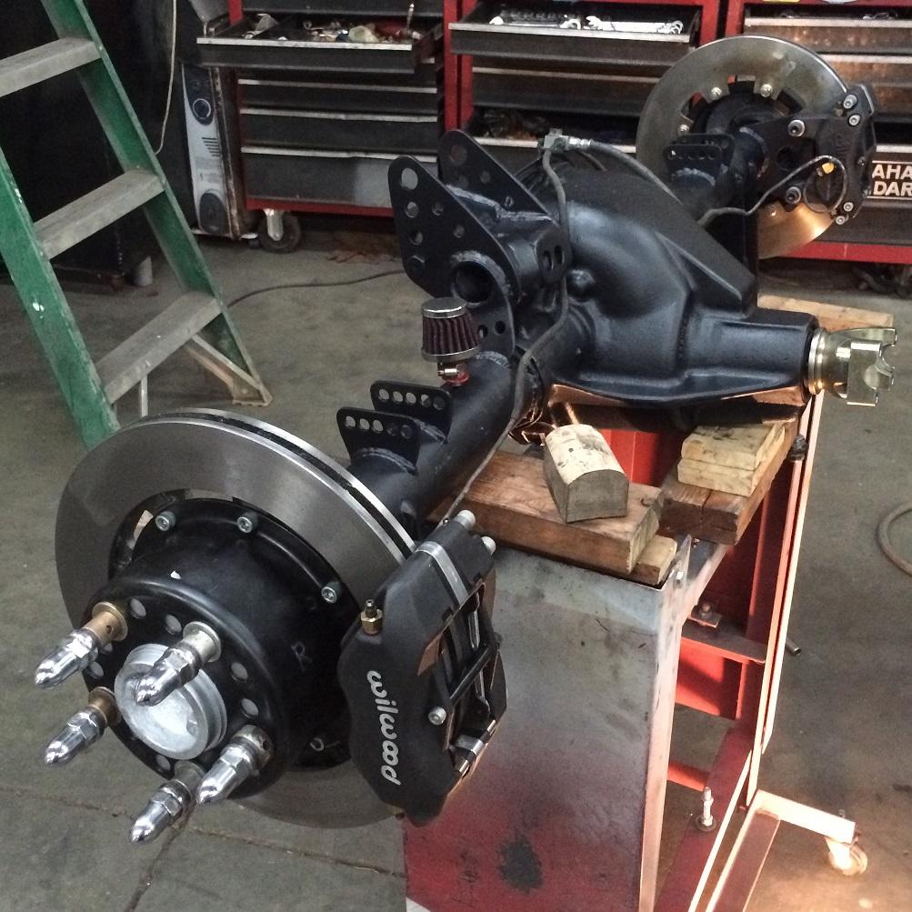
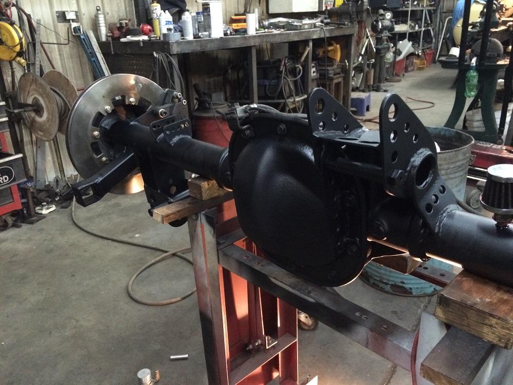
Time to revive this 2 year-old thread! This last winter brought a snowball of upgrades. The front rotors and pads were shot, so my Dad and I decided to do a brake upgrade all around with larger and wider bolt on circle track style rotors along with Wilwood Dynalite calipers. The old 7.5 GM 10 bolt was maxed out so we picked up a Ford 8.8, and it only made sense to build a new suspension for the rearend. We designed and fabricated an offset 3 link with a torque link. So far I think it has worked very well, and it seems like a major improvement. As for the brakes, they are better, but I still need to get used to them to push them to their full potential.
The old Michelin PS2s on the rear finally wore out, and they are so expensive and difficult to find that I decided to go with 315/35R17 Nitto NT05s on the rear same as the front. They are approved for 12.5 wide wheels, but that is definitely the max because they look a bit funny like the import guys who stretch tires. So far the forward bite seems better, but the sidewalls are much stiffer so I will have to experiment more with pressures. Four runs at the last autoX just was not enough to get the footprint and lateral grip/feel where I wanted. The Nittos are way off compared to the newest and even previous generation of 200 treadwear tires, but they will have to do for now.
Over the last 2 years the front suspension geometry has been tweaked slightly in an attempt to get the geometry very close to the same right to left. But the goal is to find some free time this summer to completely redo the front suspension measurements to get a solid baseline and make any necessary changes. It should be much easier and a bit more accurate the 2nd time around just because we will have some experience and a better idea of how the whole process works. I would also like to get the Scout back on some 4 corner scales to get a good baseline weight.
Pictures:
https://pattersonprints.smugmug.com/...nt-3/i-RPGxpgp
https://pattersonprints.smugmug.com/...-3/i-kfWTxpx/A
https://pattersonprints.smugmug.com/...-1/i-x7WxXMs/A
https://pattersonprints.smugmug.com/...-1/i-8BDDH7R/A
https://pattersonprints.smugmug.com/...12/i-DRtcTZ5/A
https://pattersonprints.smugmug.com/...12/i-vcvHXs7/A
Here are a few front suspension videos of the from an SCCA event last season:
https://youtu.be/xlkyaAfg8p0
https://youtu.be/WBA1VjhrrVc
And here are a rear suspension videos of the new offset 3 link in action from a recent SCCA event:
https://youtu.be/cdkWAx2g9-M
https://youtu.be/GFvP0RDfNwU
https://youtu.be/F4SYGHSKz6ITyler Gibson
There's nothing like building up an old automobile from scratch and wiping out one of these Detroit machines... That'll give you a set of emotions that will stay with you... Know what I mean? Those satisfactions are permanent...
-
1 Week Ago #30
 Registered User
- Join Date
- Jul 2007
- Location
- nw phx
- Posts
- 187
Originally Posted by AutoX_a_Truck?
sure is !!
8 years later, anything new?...life is too short, live for today, tomorrow isn't guaranteed
-

 Reply With Quote


